This is an old revision of the document!
Steve Learning about Arduino Microcontrollers
Tell complete story of circuit. (button) (potentiometer)
Introduction
First we learnt how to make simple things like LEDs
Resistor 1 (Red, Black, Red, Gold)
Resistor Value: 2000 Ohms
The light bulb on this is the least bright because it has the most resistance. So, it makes sense that this LED is the least bright out of the three.

Resistor 2 (Brown, Black, Red, Gold)
Resistor Value: 1000 Ohms The brightness is almost as bright as the on with resistor 3. That should not be becuase this resistor has a greater resistor value. It may be because I am using my hand to conduct some electricity. Therefore, bypassing the resistor. I have no idea this is just a guess.
Resistor 3 (Yellow, Purple, Brown, Gold)
Resistor Value: 470 Ohms
The brightness is almost as bright as the on with resistor 2 which is weird becuase resistor 2 has a greater resistor value and the bulb connected to resistor 2 should be less bright compared to this bulb. Again, it may be becuase I did not connect the wires properly on this circuit which resulted on the electricity not flowing properly.
.

Learning How to Measure Voltage
| Number of Bulbs | Resistor (470) | Bulb 1 | Bulb 2 | Bulb 3 | Bulb 4 | total | |
|---|---|---|---|---|---|---|---|
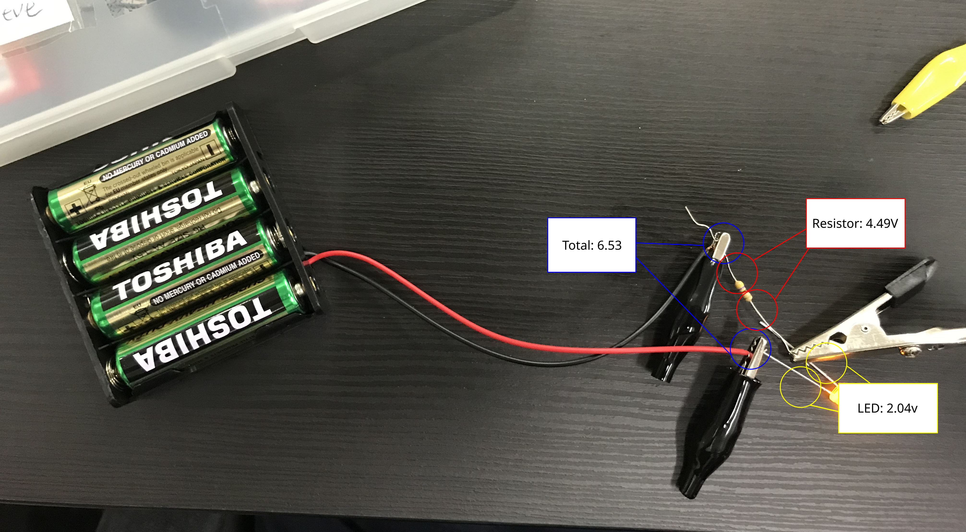
| 1 | 4.49 | 2.04 | x | x | x | 6.53 | |
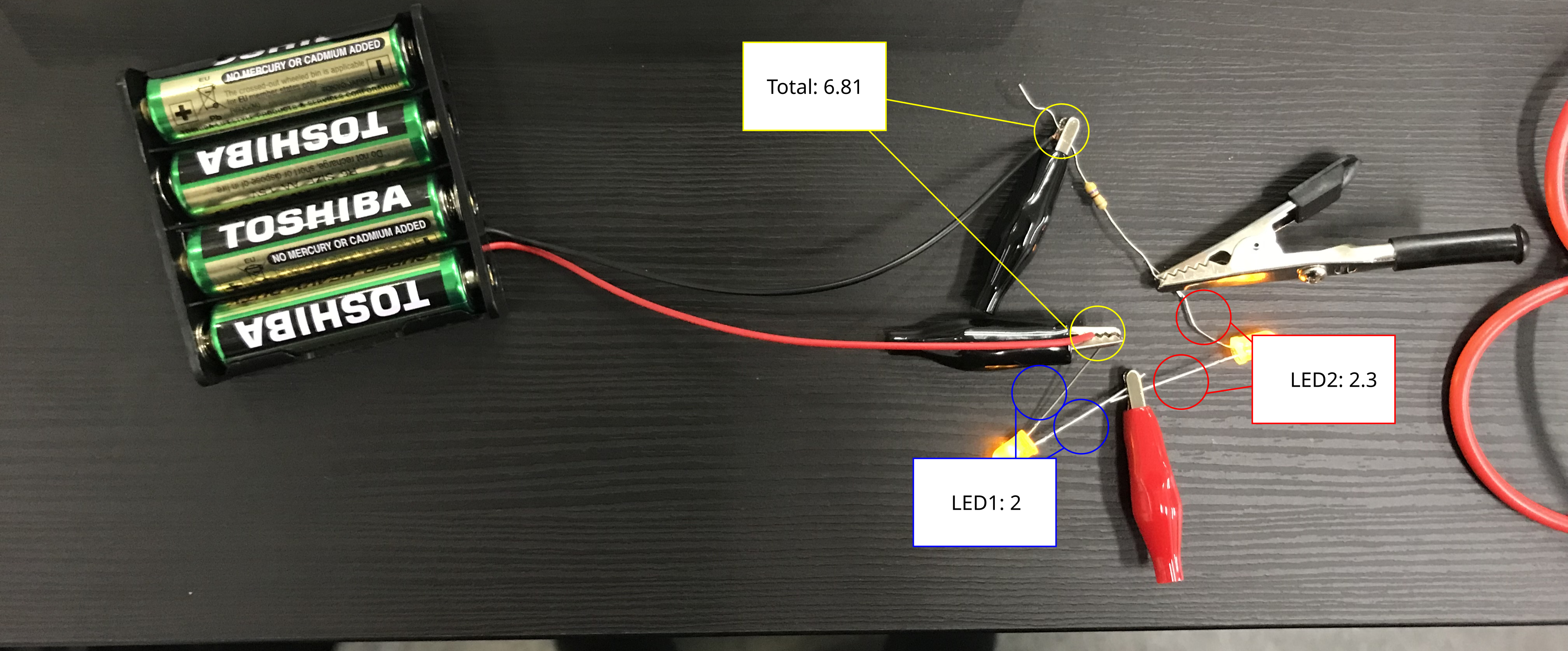
| 2 | 2.51 | 2 | 2.3 | x | x | 6.81 | |
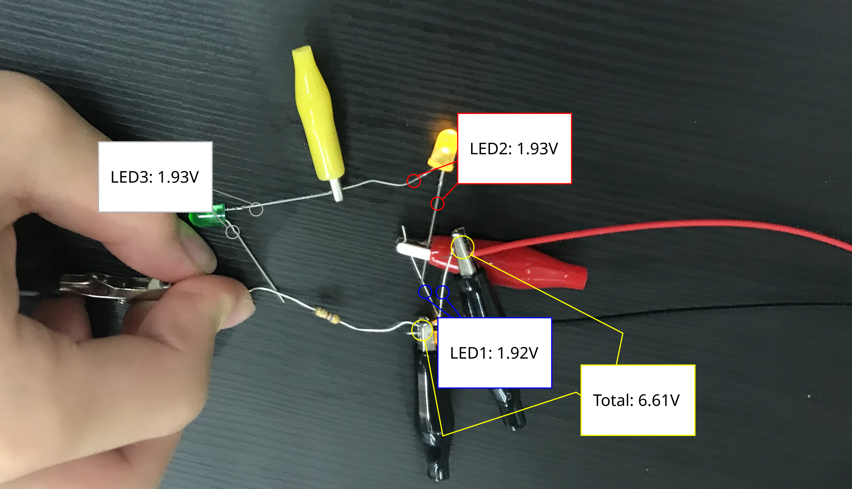
| 3 | 0.79 | 1.92 | 1.93 | 1.93 | x | 6.61 | |
| 4 | 0 | 1.66 | 1.62 | 1.64 | 1.64 | 6.6 |
1 Light Bulb
2 Light Bulb
3 Light Bulb
4 Light Bulb
It was weird when the I measured the volts of the resistance it was 0. I think it is becuase all the light bulbs have used up all the electrcity and by the time the elctricity gets to the resistor, there was no more electricity left to resist.

COnclusions
The amount of current recroded at the resistores decreases as the amount of LEDs increases. The totoal current stays about the same.
The amount of current recorded next to the LEDs decreases as the amount of LEDs increases.
Testing with Potentiometer(A2k) with Terminal 1 and 2
Then, we learnt how to use potentiometers. For this one, I followed the instructions and got the results I expected when I turned the knob. Turning it to one side dimmed the light. Turning it to the other side increased the brightness.
Testing Potentiometer(A2k) with Terminal 2 and 3
At first, I thought the difference was it was brighter this time. However, after a demonstration, I realised that the direction to dim the light and increase the brightness has changed. That was very hard to spot.
we learnt the basics. Resistors, potentiometers, and drawing diagrams
Learning More Tools
Things like, switches, potentiometers, capacitors, and transistors.
Switch
- Mode 1:
- The left and the right forms a closed circuit.
- Mode 2:
- The middle and one of the side forms a closed curcuit
New resistor : 150Ohms
Testing with multiple LEDS
Testing with a switch and potentiometer
Alternationg circuit with switch

 On one side of the switch when it is up, the left side and the right side. When the switch is donw, the middle and the right side of the switch form a closed circuit. So, to get alternating lights, the power is always needed so it shuld be connected to the right hole. To ensure the breadboard does not mess with the swith, the I need to make sure the other side is not plugged in.
Breadboard explanation
The rows from that are of english letters are connected so if one of the holes on that row is powered all of the holes are powered. However, the two lines on the side are different. If one of the point is powered all the ones on the same collum is powered. Only for those four rows only. So, the breadboard is very useful when making intricate ciruits that need to be squashed in small spaces. Also, with this alligator clips are now useless.
Capacitor
Results
| Resistor amounts | time | |
|---|---|---|
| 470 | 1s | |
| 2K | 5.8s | |
| 27K | 1.14m | |
| 50K (new capacitor) | 3.5m | |
| 100K | 4.23m |
My results are a bit weird becuase halfway through, I though that my capacitor was broken. I tried to charge it using the 227k resistor but it would only go up to 3. something no matter what I did. So, when I got a new capacitor evevrything worked. However, after Dr.Bell tested my old capacitor, he said it was fine and not broken.
Charging Capacitor
Discharging capacitor
As you increase the resistance, what happens to the charging time? The charging time increases. When the amount of voltage in the capacitor increases, the charging rate of the capacitor increases.
Transistor
Modifying the AC adapter to work with your breadboard
Circuit with transistor and switch
The transistor makes a closed circuit with the one on the left and right if there is power going through the middle one.
Circuit with transistor without switch
This works because my hand acts like the switch. When my hand is touching the wires, I conduct the electricity. When my hand is not there the circuit is open and the LED does not light up
With That, We Build A Few Simple Systems
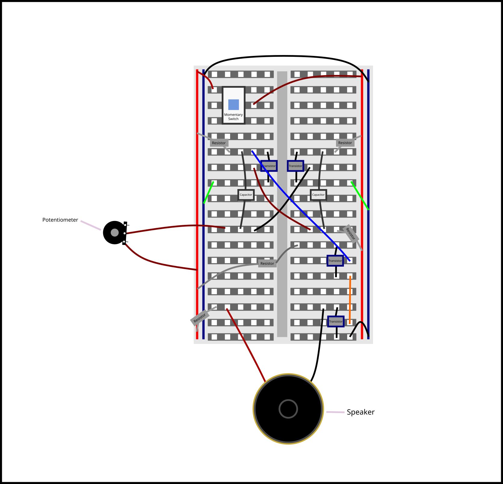
Steve building an oscillator
Components:
- Capacitor *2
- Transistor
- Wires *5
- Staple bullets wires *2
- 230 ohm resistor *2
- 9800 9.8k ohm resistor *2
- Potentiometer left high right low.
Basic oscillator
 Both LEDs almost have a closed circuit they are blocked by a transistor. We want to activate the transistor by discharging a capacitor. So, we have to charge the capacitor first. Both capacitors do not charge at the same speed because, even though the resistors should have the same amount of resistance, they are not built perfectly so they do not. One of the capacitors will charge faster which will allow it to discharge earlier than the other. That would cause one of the LEDs to light up earlier than the other. When the other capacitor is ready to discharge, the first capacitor has already finished discharging which causes the first LED to turn off. That is how the circuit to have alternating LEDs.
With Potentiometer

 The resistor controls the blinking speed because, the resistor controls speed the capacitor charges at. If the charging of capacitor slows down, the LED will need more time before it can turn on. I can add resistance by adding a resistor with greater resistance and doing that would slow down the current. To change the amount of resistance without swapping out parts, I can use a potentiometer.
Using A potentiometer
Speaker with Potentiometer
Speaker with Switch
Circuit Illustration and Explanations
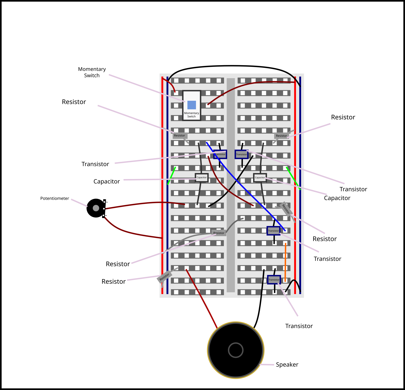
Resistor: Resist flow of current. Resistance is measured in ohms (Omega).
Transistor: An electrical component that can switch circuits on and off and amplify signals
Capacitor: Stores energy like a battery but discharges much faster
Speaker: When it has electricity, it will move the cone back and forth which creates air pressure that we perceive as sound.
Potentiometer: An electrical component that can change the amount of resistance.
Momentary Switch: A switch that creates a circuit only when presses.
Connecting Our Circuits With Computers
Testing Arduino
Testing Arduino With Lights
Testing arduino with speaker
Testing With Force Sensitive Resistor
Projects
Toilet Flusher
This is a button I made with the arduino for the Old Man Simulation. It works like this: When I hold donw the button , it starts a time and plays a little sound and when the simulation is done, the person clicks on the button which plays the flush sound effect by lorenzgillner on freesound website. Here is the video:

